Join the AI Workshop and learn to build real-world apps with AI. A hands-on, practical program to level up your skills.
A potentiometer is a tiny component that has 3 connectors: 2 on one side, 1 on the other side:
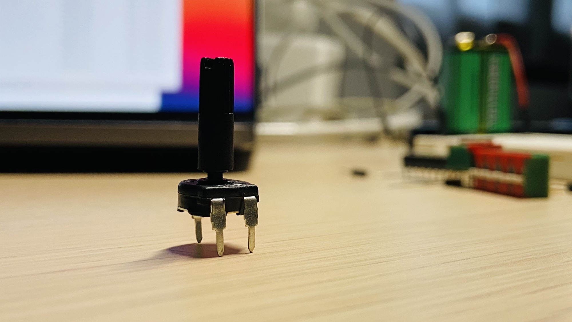
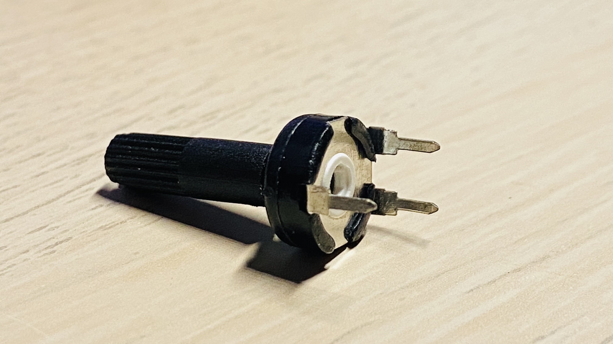
The two connectors are the input, they are connected to the negative and to the positive, and the opposite one is the output.
By rotating the potentiometer we can get on the output a fraction of the voltage difference applied to the input pins.
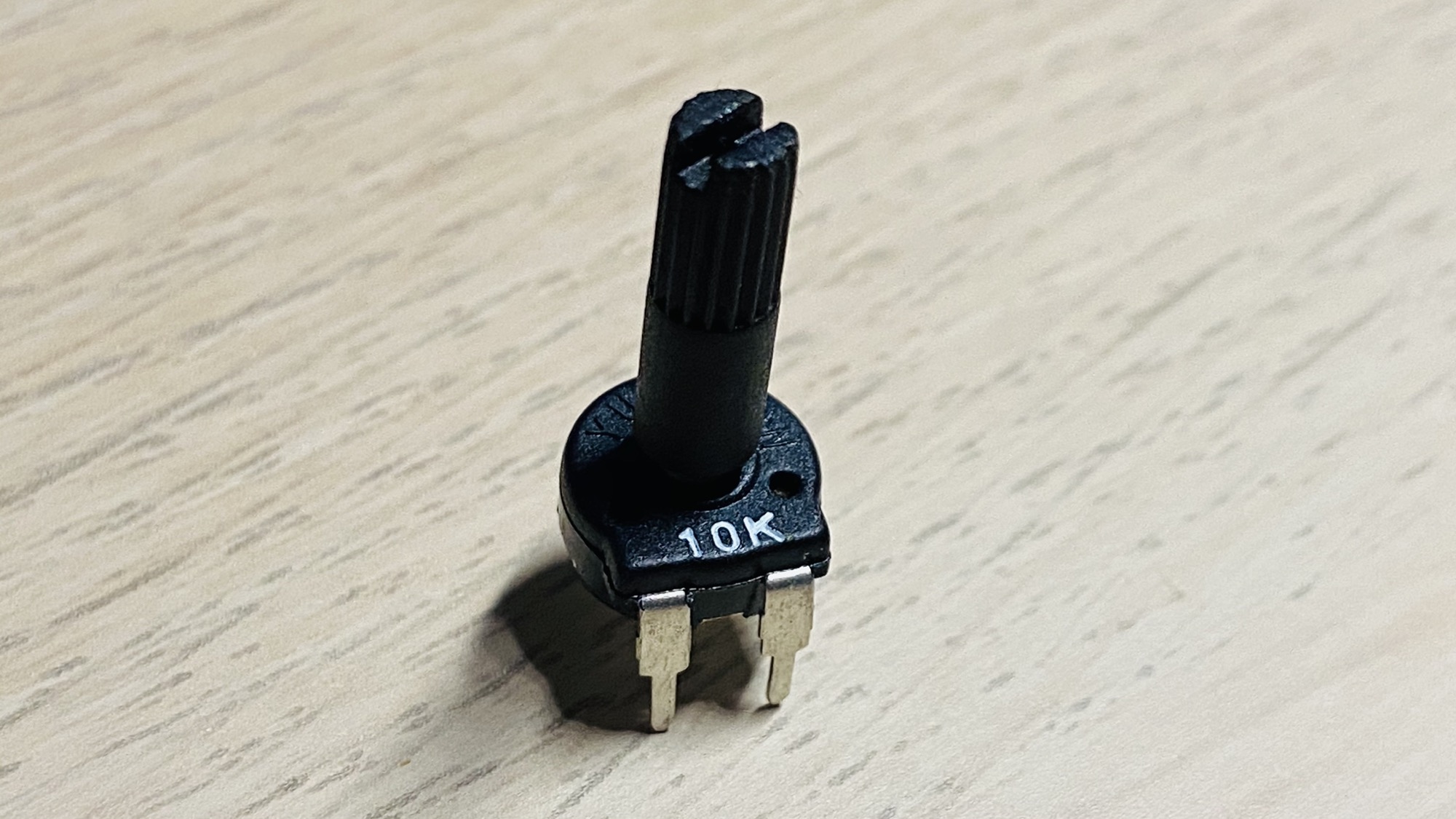
This is because the potentiometer is a variable resistor whose resistance we can adjust. In this case I have a 10kΩ potentiometer:
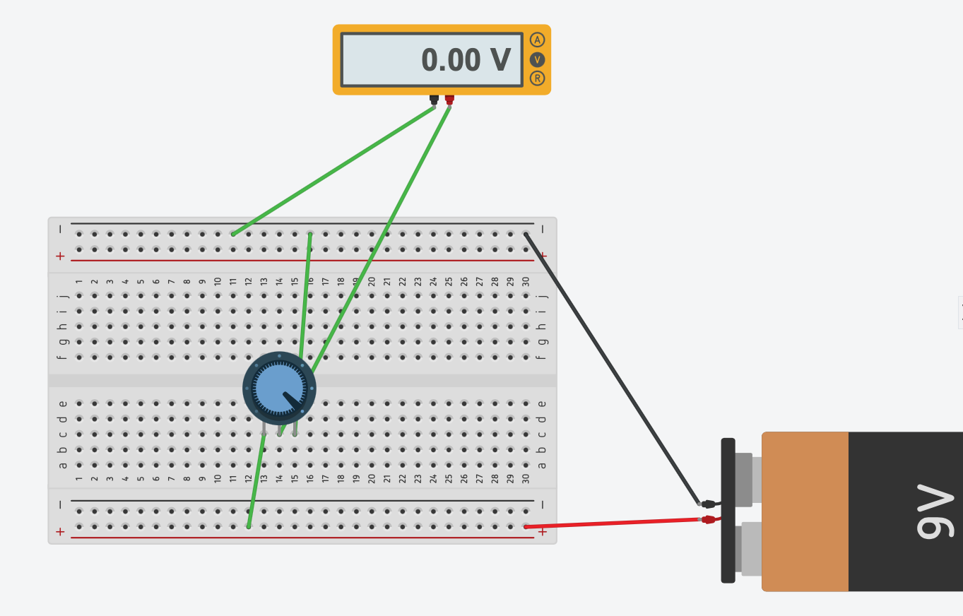
See this simulation: if we have the potentiometer at full left (counterclockwise), on the output pin we have a 9V difference between the output pin and ground, because the potentiometer is working at 100% as a 10kΩ resistance and absorbs all the current:
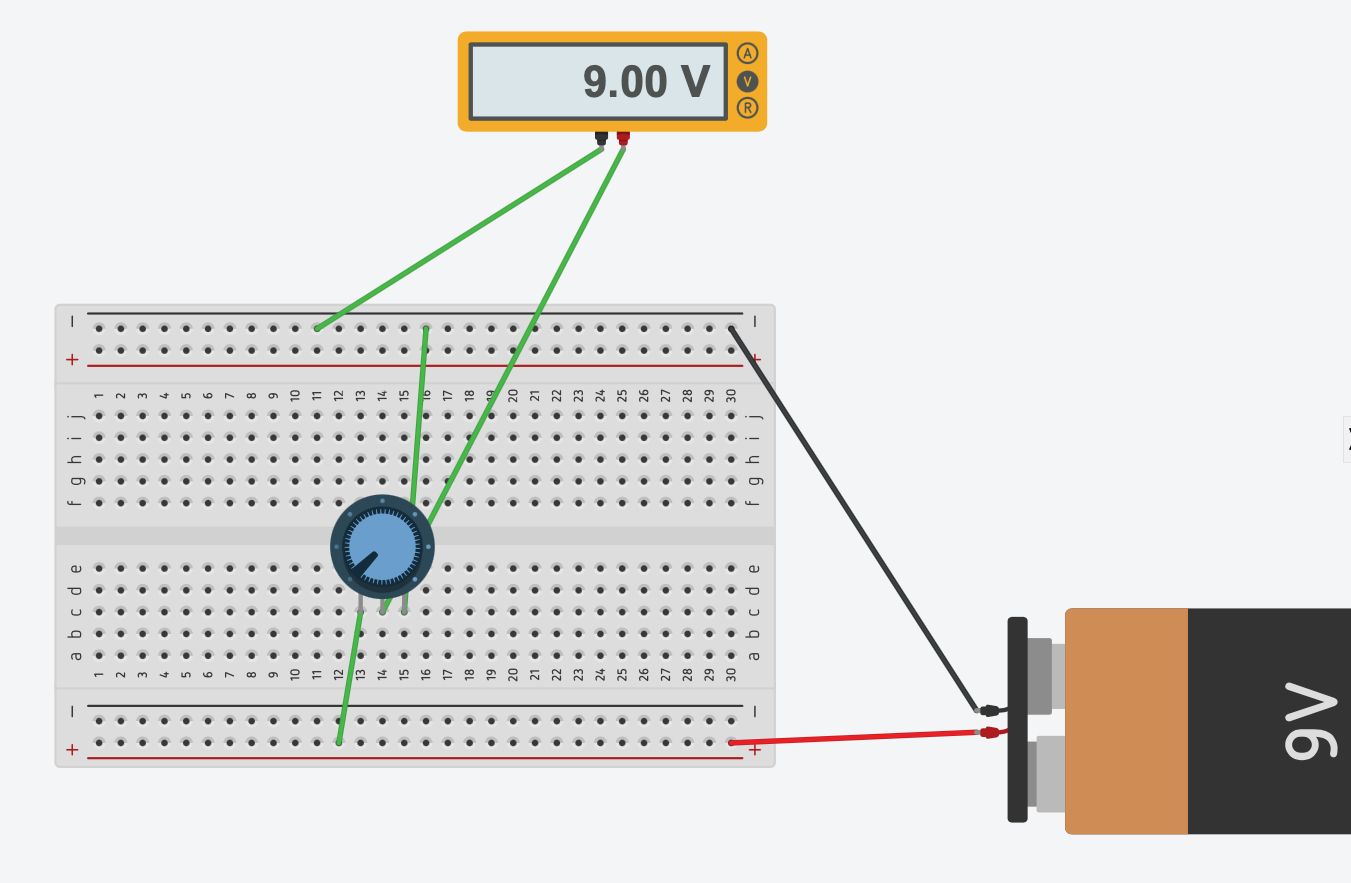
If we turn the potentiometer to full right, on the output pin we have 9V because the potentiometer does not absorb any current. It works like a wire, applying 0 resistance.
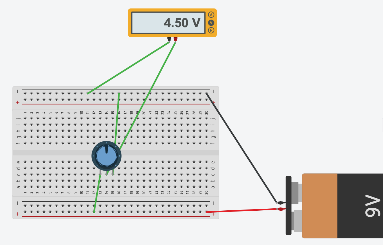
With the potentiometer at 50%, we get half of the input voltage on the output pin:
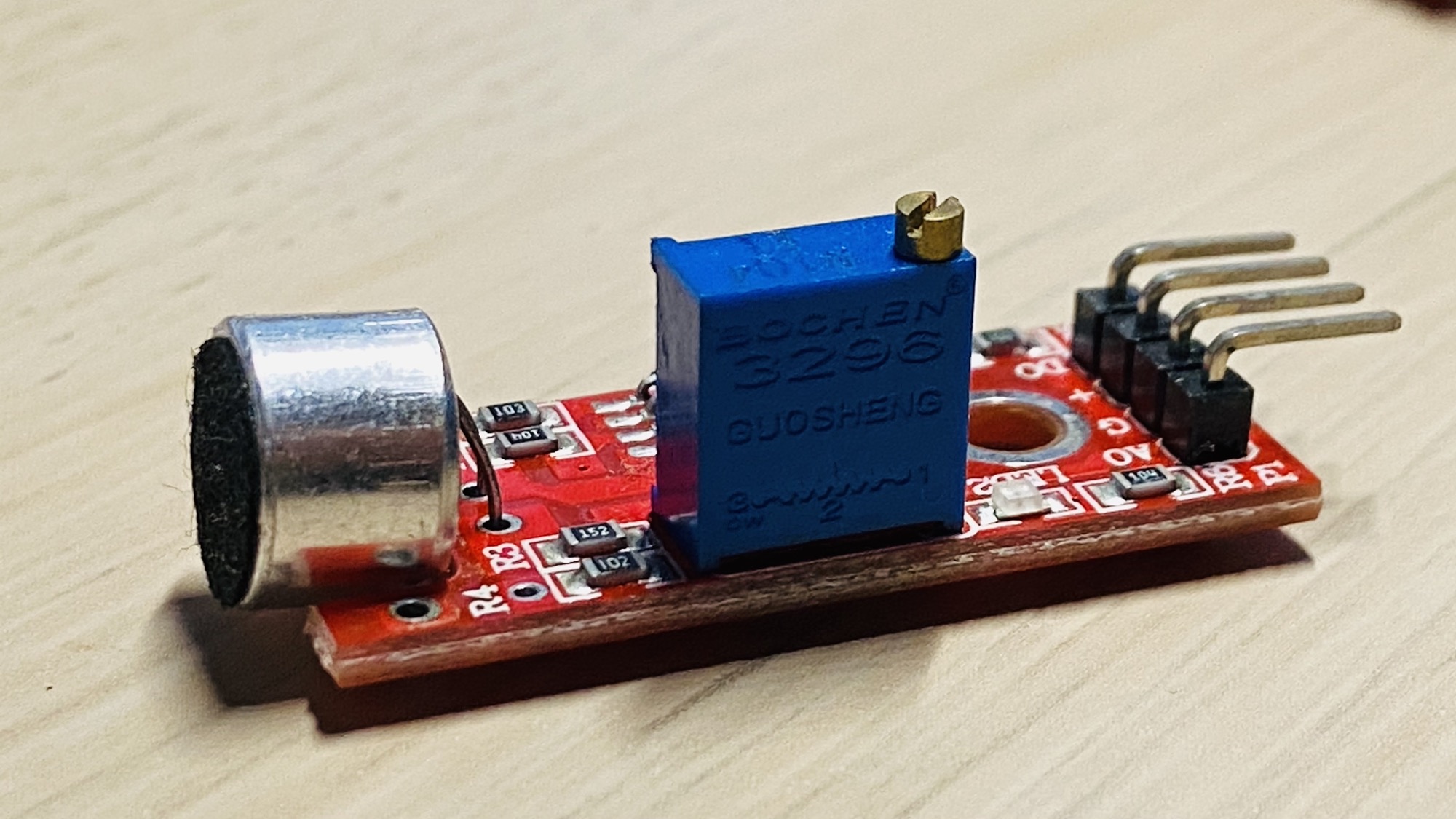
Potentiometers are handy for many reasons on their own, but they are also used in integrated circuits to help us regulate the output, like in this sound sensor where the potentiometer is the blue box we can adjust with a screwdriver:
Lessons in this unit:
| 0: | Introduction |
| 1: | Breadboard Power Supply Module |
| 2: | Resistors |
| 3: | LEDs |
| 4: | RGB LEDs |
| 5: | Diodes |
| 6: | Buttons |
| 7: | ▶︎ Potentiometers |
| 8: | Buzzers |
| 9: | Servo Motors |
| 10: | Analog Joystick |
| 11: | The DHT11 temperature and humidity sensor |
| 12: | The 1602 LCD Display |