Join the AI Workshop and learn to build real-world apps with AI. A hands-on, practical program to level up your skills.
In this lesson we’ll show you how to build an LED dimmer with a potentiometer.
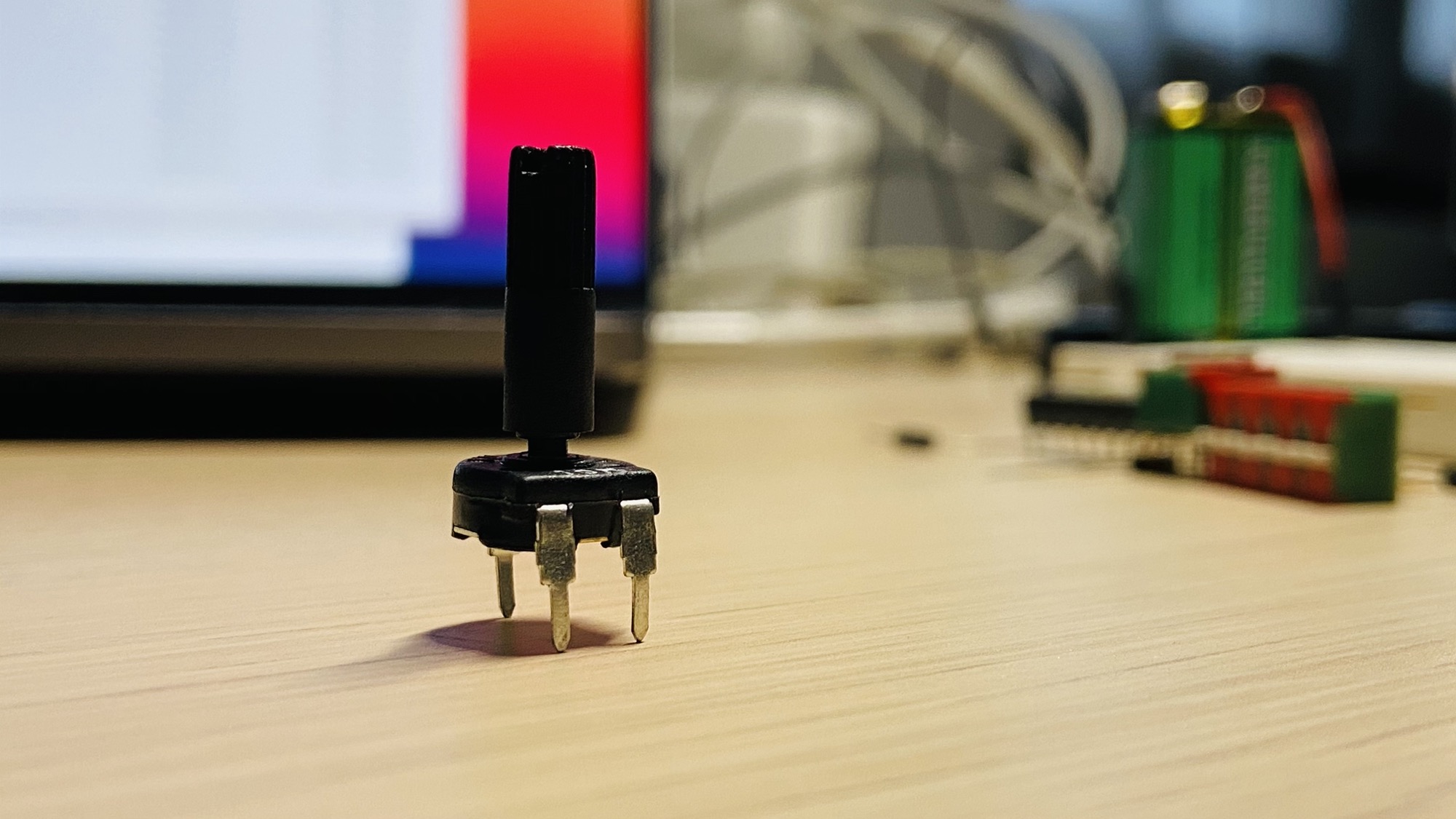
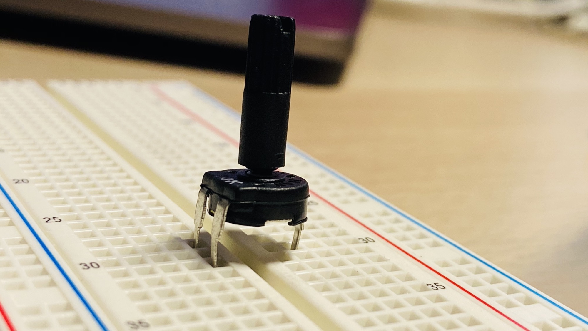
You need 4 things: a potentiometer, like this 10kΩ one:
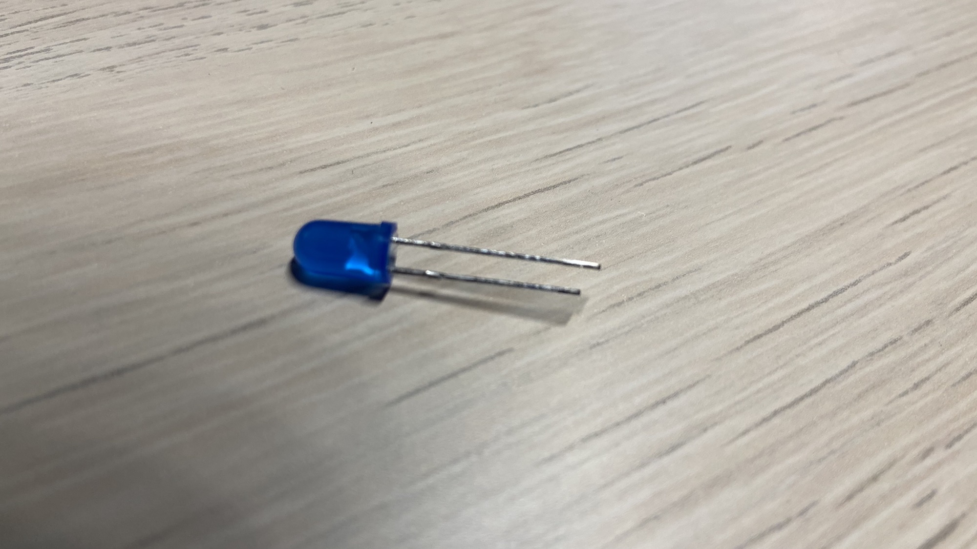
A 5mm LED, any color you like:
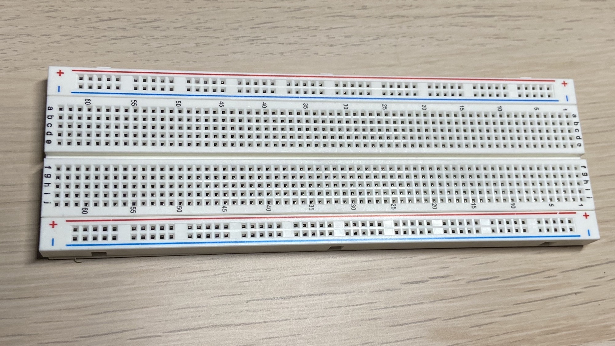
A breadboard, where we put our components on:
And a battery. I use a 9V battery:

Plus some wires.
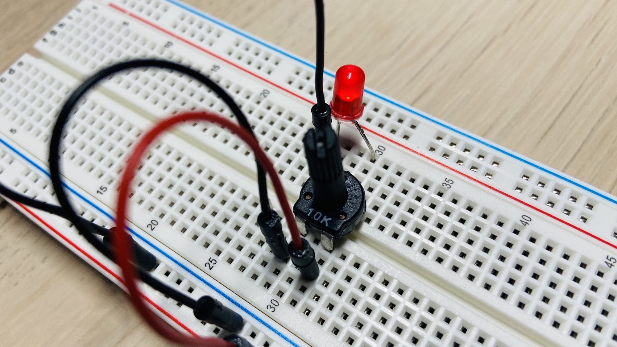
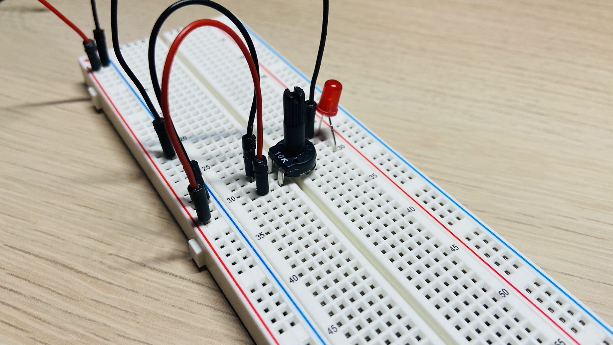
Start by putting the potentiometer on the board, in any place you want, with the 2 input pins on one side of the board, and 1 output pin on the other side:
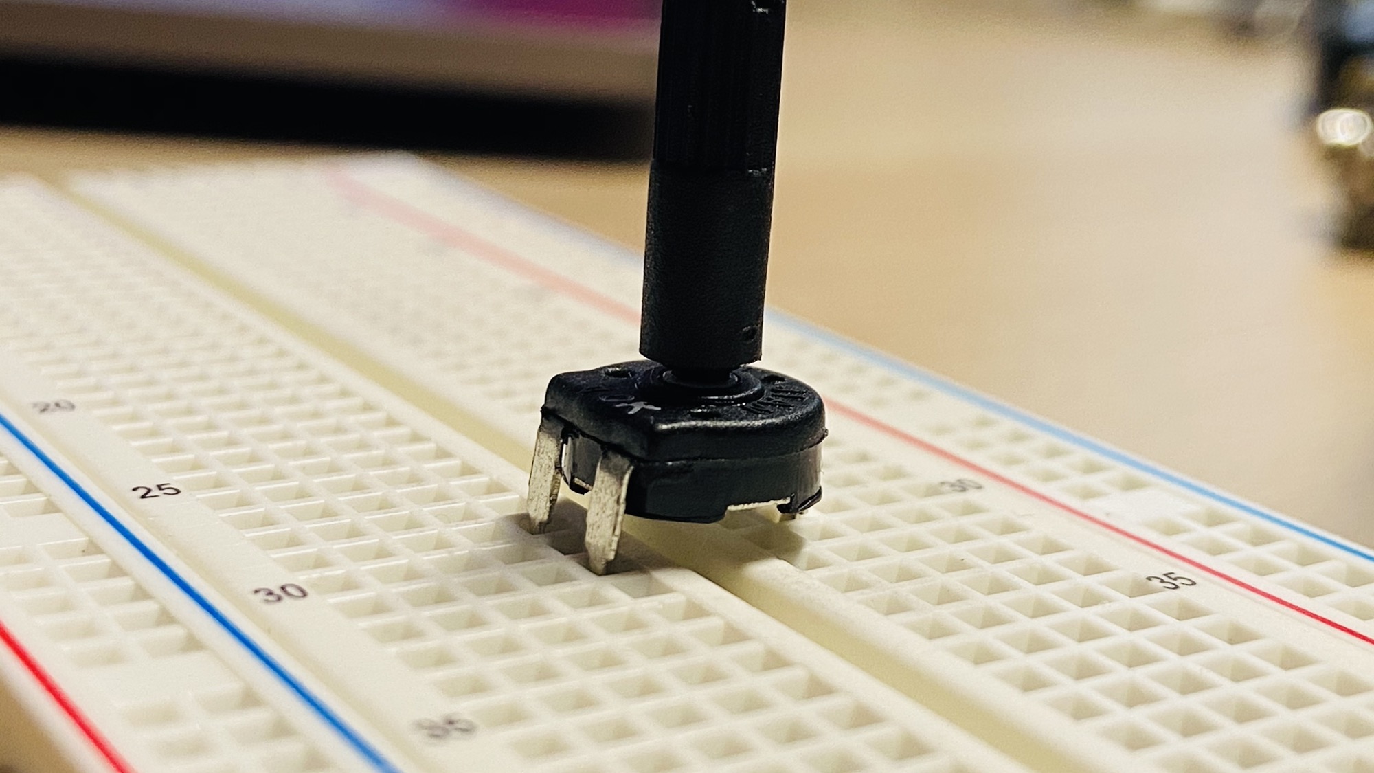
Press it down to connect it to the breadboard:
Now connect the - pin to the blue line of the breadboard which we’ll connect to the negative pole of the battery, and the + pin to red line which we’ll later connect to the + pole of the 9V battery.
I use by convention a black wire for the - (GND) and a red wire for the positive +.
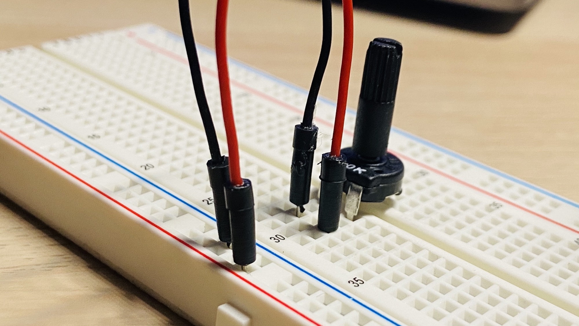
Make sure the potentiometer is completely turned to the left, counterclockwise.
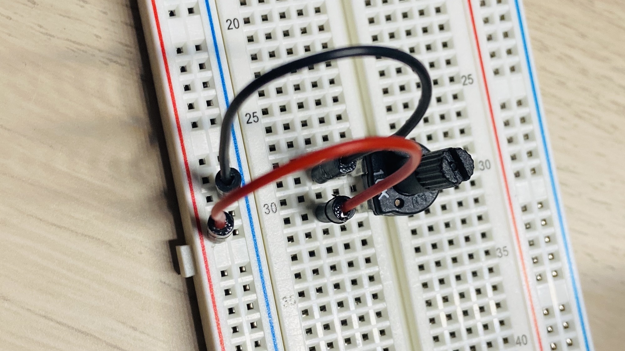
Now connect a LED to the output pin, put the longest wire of the LED, the anode, on the same row. Then connect the cathode, the shortest wire, to the - blue line of the breadboard:
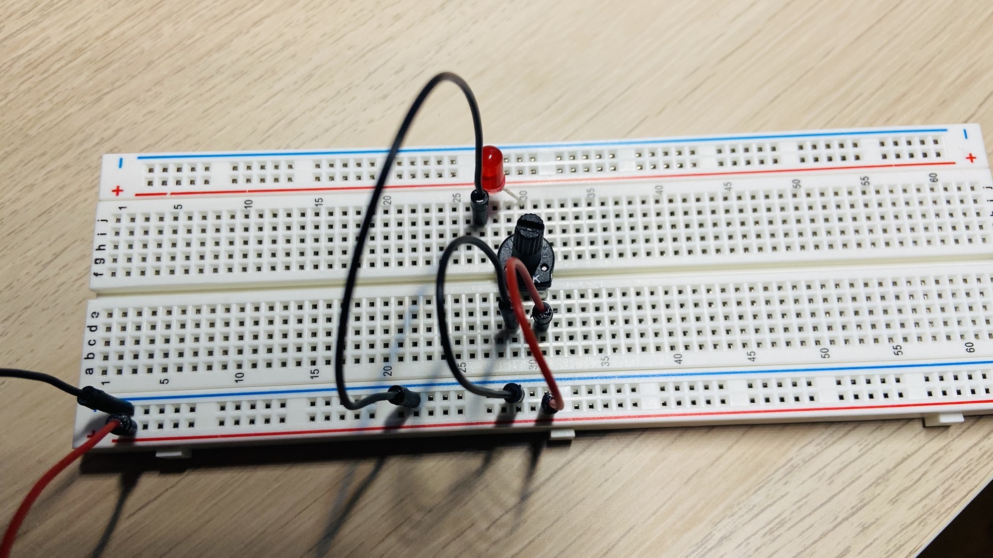
Great, now connect a 9V battery and you’ll see the LED still turned OFF (assuming you turned the potentiometer all the way to the left, counterclockwise, which acts as a 10kΩ resistance in the example).
Be careful not to turn the potentiometer all the way to the right, or the LED could be damaged as the current will be too much to handle.
Rotate it slightly to the right and you’ll start to see the light turn on, getting more intense as you turn the potentiometer further to the right.